The IDPU is mounted internal to the Parker Solar Probe (PSP), on the inside of the bulkhead to which the WIM is mounted. It is a two-slice assembly consisting of the Data Processing Unit (DPU) slice and the Low Voltage Power Supply (LVPS) slice enclosed in a Magnesium Alloy package (Fig. 22). The LVPS provides secondary power to the WIM and the DPU. It receives 28 V switched power from the spacecraft and provides power control for the operational heaters. The DPU provides the primary interface to the spacecraft, breaking complex scheduled command sequences into primitive operational commands for the two cameras. The DPU commands the WIM, processes, compresses and, stores the WISPR images, distributes and collects housekeeping information and communicates with the spacecraft. The DPU also controls the operational heaters. The spacecraft controls survival heater power to the WISPR instrument directly and provides the door opening service. The WISPR IDPU derives its heritage from similar units on RBSP, CRISM and, MESSENGER.
IDPU Electrical
The figure below (Spacecraft-IDPU-WIM Harness and connectors) shows the connections from the spacecraft to the WIM, which consist of 9 cables. There is a power cable from the spacecraft to LVPS, 2 SpaceWire cables from the spacecraft to the DPU, a power cable from LVPS to WIM, Camera Interface cable from WIM to DPU, operational heater cable from LVPS to WIM, housekeeping cable from WIM to IDPU, survival heater cable from spacecraft to WIM, and the spacecraft-monitored thermistors from WIM to spacecraft.

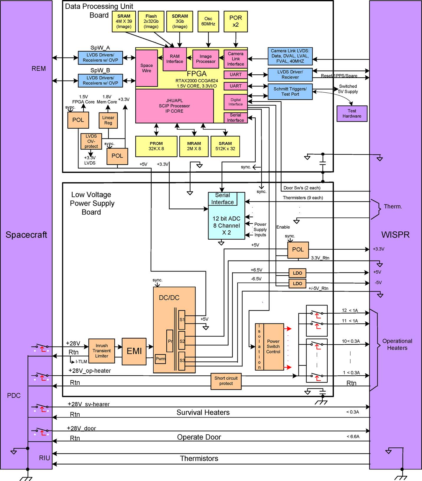
The image below (IDPU Electrical Block Diagram) shows the electrical block diagram of the WISPR IDPU. The LVPS is implemented on a single 6.5__ °ø 4__ board and contains an inrush transient limiter, EMI Filter, a DV-to-DC converter (5VDC to IDPU, 3.3VDC digital and °æ6.6 VDC analog supplies to WIM), heater switch control, housekeeping ADC System, and convertor synchronization and ADC system control (provided by the digital board).
The DPU is implemented on a 6.5__ °ø 4__ board and contains point-of-load convertors, memory modules for the processor and data processing and an Actel RTAX2000 FPGA. The DPU FPGA contains the SKIP processor, which is a programmable FORTH processor, the Image processor, and all the attached interfaces as shown in Fig. 24. The image processing is performed by hardware in the FPGA. The SKIP processor handles housekeeping, and manages the image processor based on schedules commanded by the ground. The FPGA contains:
- Clock and Reset distribution to generate Master Reset from redundant power-on reset chips, External Test Reset, and Internal Watchdog.
- 30 MHz SpaceWire and image processing clock.
- 7.5 MHz SCIP processor clock.
- Multiple memory interfaces.
- Image processor w/digital scope accessible test port.
- SCIP processor.
- Core I/O, which includes: Camera/Test UARTs, LVPS controls for heater switches and housekeeping ADCs, Voltage supply clocks, RMAP and SpaceWire node, and a40 MHz LVDS camera interface (FIFO to image processor).

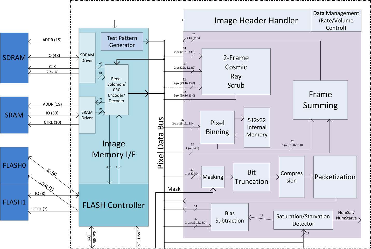
All image processing takes place in the image processor (see block diagram below). The processor contains modules for common operations such as bias subtraction, pixel binning, compression, and packetization as well as modules specific to WISPR operations such as frame summing and a cosmic ray scrub operating on two images at a time. It has access to a 3 Gb SDRAM image storage, a 160 Mb SRAM image buffer, and 33.75 Gb of flash bulk storage, sufficient to store the full WISPR data volume for two orbits. The data are transferred to the spacecraft via SpaceWire at an average rate of 250 kbps.
IDPU Mechanical
The overall IDPU dimension is 21.2 cm (L) °ø 11.6 cm (H) °ø 5 cm (D). It weighs 1070 g and consumes 7.3 W (current best estimate). It is designed to operate between −25 ◦C and 65 ◦C and survive from −30 ◦C to 70 ◦C. The chassis, covers and shielding plate are made of 20 mm thick Mg ZK60A and is put together using Ti alloy (6AL4V). The preliminary structural analysis shows that the primary box and board modes are 192 Hz and 150 Hz, which exceed the 80 Hz minimum frequency requirement and demonstrate sufficient frequency separation.

