WISPR is designed, developed and will be operated by the Solar & Heliospheric Physics` Branch at the Naval Research Laboratory (NRL). As the only imaging instrument onboard PSP, the WISPR design is guided by two overarching objectives: (1) WISPR should provide the crucial link between the in-situ PSP observations and the large scale structure of the corona that is needed to address PSP science, and (2) WISPR should enhance the scientific return of the mission with trailblazing observations of two-dimensional electron density power spectra, interplanetary dust, and sungrazing comets. WISPR will provide continuous synoptic observations of the inner heliosphere, imaging both the quasi-steady flow and transient disturbances in the solar wind by observing visible sunlight scattered by electrons in the solar wind. Its wide field of view (FOV) will encompass both the inner corona and the plasma in the vicinity of the spacecraft. TheWISPR FOV is centered on the ecliptic plane but it is offset from the Sun, and covers a range of elongation angles from 13.5◦ to 108◦ with a spatial resolution of 6.4 arcmin (Fig. 1).
| Telescope | Heliocentric Distance (AU) |
FOV (Rs, AUeq) |
Spatial Resolution (arcsec AUeq) |
Cadence (min) |
|---|---|---|---|---|
| WISPR | 0.25 | 9.5-83 | 94 | 60 |
| 0.1 | 4.0-41 | 26 | 7 | |
| 0.044 | 2.2-20 | 17 | 0.05 | |
| SoloHI | 0.28 | 5.1-47 | 25 | 5 |
| LASCO/C2 | 1 | 2.2-6 | 24 | 24 |
| SECCHI/COR2 | 1 | 2.5-15 | 30 | 15 |
| SECCHI/HI1 | 1 | 15-90 | 108 | 40 |
| SECCHI/HI2 | 1 | 74-337 | 25 | 120 |
| SMEI | 1 | 74–>337 | 1440 | 102 |
Table 1 compares (above) the WISPR FOV and resolution at different locations in the PSP orbit with those of current coronal imagers, using 1 AU equivalent quantities (AUeq) to provide a common comparison baseline. The numbers refer to objects far from the telescopes. Obviously, the effective resolution for near-field objects will be better as long as those objects are resolved. WISPR’s perihelion FOV extends both closer and further from the Sun than the Sun-Earth Connection Coronal and Heliospheric Investigation (SECCHI; Howard et al. 2008) COR2 coronagraph, at about twice the spatial resolution. It includes the Alfvén point, which is expected to lie between 10–30 Rs based on theoretical considerations (see DeForest et al. 2014 and references therein) and is likely never below 5.5 Rs (Sheeley and Wang 2002). Such a wide FOV and high resolution is vital to the success of the PSP mission. Our studies of coronal structure with STEREO and SOHO have shown that there is abundant structure at the resolution limits of those instruments, both in streamers and in CMEs. An instrument unable to resolve these structures would only provide the large-scale context for in-situ measurements, a limiting role discussed in the Solar Probe STDT report.1 The WISPR science program extends beyond that to the study of the substructures of streamer current sheets and CMEs, and to the study of turbulence and shocks as discussed in detail in the next section.
The high-resolution observations will image both co-rotating and transient structures (e.g., CMEs, jets, and plumes in coronal holes) as these structures propagate through the inner corona and ultimately pass over the PSP spacecraft. The rapidly changing FOV will enable detailed tomographic reconstructions of the large and small-scale structure of the background corona. Thus, WISPR will provide both broad and detailed context for interpreting the in-situ PSP measurements. Note that WISPR’s nominal resolution of 17 arcsec (AUeq) at closest perihelion is a lower limit. Structures approaching the spacecraft will be imaged at much higher resolution. This provides the second major rationale for designing WISPR with such high resolution. To take full advantage of the high resolution, WISPR is mounted on the forward, ramside of the spacecraft.
The solar wind structures observed by WISPR move radially outward at speeds equal to or exceeding the orbital speed of PSP at perihelion (∼200 km/s). The ram-side mounted WISPR instrument will therefore image structures prior to their in-situ measurement, with increasing resolution, as they rise up from the Sun towards PSP. This allows WISPR to point close to the solar disk and simultaneously image these local structures. The combination of WISPR’s high resolution and ram-side mounting allow us to image and study dynamical processes which evolve as the PSP spacecraft approaches and then flies through them, enhancing WISPR’s capabilities to support the in-situ measurements of both static and dynamical structures. WISPR will observe the Thomson-scattered light from the solar wind electrons. This scattering process has a sensitivity dependence on the geometry between the Sun, observer and scattering electron. Vourlidas and Howard (2006) have shown that the observing geometry must be taken into account for the proper interpretation of coronagraph and heliospheric imager observations. They introduced the concept of the Thomson surface, which denotes the location of maximum scattering efficiency. Solar wind features at progressively large angular distances from the Thomson surface scatter less than features close to the surface. Because the Thomson surface varies with the Sun-observer distance, it is especially important to understand its effects on the WISPR science analysis.
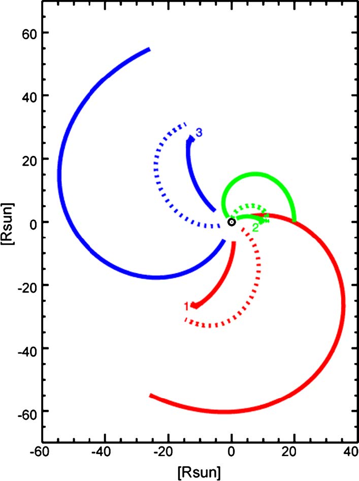
The mission design of the PSP is highly unusual for an imaging instrument due to the rapidly changing orbit and the very close perihelia. An important consequence of Thomson scattering effect is that the locus of maximum scattering passes through the spacecraft. This means that at the elongation angle of 90◦, WISPR becomes an ‘in-situ imager’. This effect was first noted in the Helios analysis of the 90◦ photometer, which detected an increase in the intensity whenever a CME crossed the spacecraft (Jackson and Leinert 1985). These effects are shown in Fig. 2 for three locations during an orbit at closest perihelion. WISPR is located on the ram-side and we plot the full 180◦ longitudinal scan, rather than the 90◦ WIRSP FOV, for completeness. Each color denotes a different part of the orbit and the numbers mark the location of the S/C at that moment. The three contours in each color mark, in increasing distance from the S/C, the 5 %, 50 %, and 95 % of the cumulative brightness along a given elongation (or LOS).
At the start of the observing period (marked by ‘1’), plasma as far as 40 Rs from the spacecraft contributes to the emission. But at perihelion (‘2’), only emission within 10 Rs is important. Also, the 50 % emission is almost independent of the elongation while the LOS extends further for elongation >90◦. These plots show that the forward quadrant is well observed by the instrument and thus will detect the CMEs, shocks, plasma sheets, that the S/C will then pass through. These plots show that considerable part of the emission at large elongations comes from structures near the S/C (50 % curves). At the same time, the SNR drops quickly with increasing heliocentric distances leading to longer integration times (>60 min, Table 2). Therefore, imaging at large elongations provides less useful tomographic information. More details on the Thomson scattering effects and their implications on Solar Orbiter and PSP missions will be discussed in Vourlidas et al. (2015).